---- FLIP - FLOP ----
Flip-flop is a digital chain that is used to store one bit of semi-permanent until there is a command to delete or change the contents of the stored bit.Basic principles of the flip-flop is a basic component electronics such as transistor,1. Save the binary number 2. Tattoo 3 credits. synchronize a series of arithmetic
praktikum in this we can use the tool and materials:
1. Digital Trainer kit
2. Tools Kit (Long Nose and Tang pieces)
3. A TTL IC-K Flip-Flop (7473) 4. Cable jumpers secukupnya
Flip - Flop has many types such as RS flip - flop, JK flip - flop, JK flip - flop with preset and CLEAR, D flip - flop and Master-Slave flip - flop, but is more often used are:
A. RS Flip - Flop
Have two terms in use, namely: its output is input into the other, and the output should be more than satu.Flip RS-flop is a series of basic of all types of flip-flop that is.There are various series of RS flip-flop, in this experiment RS flip-flop is arranged from the four 2 input NAND gate. Two input flip-flop is the S (set) and R (reset), and the two are keluarannya Q and Q '.
-> Diagram RS

Cable scheme NAND

First of all pairs of IC 7400 on the bread board, then connect the switch and the IC cables available, connect the IC to the ground, 5V power input, and also output to LED.Input R connected to the foot 1, S Input is connected to the foot 5, Voltage / VCC is connected to the leg 14, connected on 2 feet 6 feet.
-> Tabel Kebenaran

B. JK Flip - Flop
JK flip-flop was a refinement of the RS flip-flop, especially to overcome the oscillation problem, namely the presence of feedback, and problem conditions prohibited.on the condition of J and K inputs berlogika 1, that condition will make the output to be at variance with the previous output condition or known by the term Toggle.
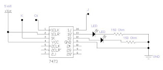
-> Diagram JK

Cable scheme JK

First install the IC in the bread board, then connect the switch and the IC cables available, connect the IC to the ground, 5V power input, and also output to LED. Input A is connected to the leg 14,
input clock connected to the foot 1, K input is connected to the foot 3, Voltage / VCC is connected to the foot 4, D / CLEAR worth 1 to 2 feet on the IC 7473.
Truth Table:

.jpg)